To prove this simply connect a volt meter to your amplifier and set the sine wave generator frequency to 60 Hz. Note the reading on the volt meter. Now change the sine wave generator frequency to 20 Hz and note the reading on the volt meter. Don't be too surprised if the reading has gone down a little from the original 60 Hz reading.
I will show you how you can overcome this problem by performing a calibration sweep before loudspeaker testing begins.
Now Set up the stuff as shown in Figure 4, but substitute the 10 ohm resistor for the loudspeaker. Set the sine wave generator to 50 Hz and adjust the volume control on the amplifier or current source module so that the reading across the 10 ohm resistor is 10 mV per ohm, i.e. if your 10 ohm resistor actually measured 10.2 ohms set the volume control to give 102 mV.
Record frequency and volt meter readings every 5 Hz from 20 Hz to 100 Hz (for a bass drive unit) on a spreadsheet or piece of paper, remember not to touch the volume control at any point. Now take the 50 Hz reading as the baseline and subtract the volt meter reading for that frequency from all the other readings. This gives you your calibration data which shows you how far out your setup is. To obtain calibration data for in-between each reading you can make an educated guess, but if you used a spreadsheet you can use the averaging function or produce a large graph which can be read across. The following steps are for producing a suitable graph using OpenOffice (version 3.x) (a great, free, office package) Calc spreadsheet:
If you didn't do so prior to calibration, measure the resistance of your loudspeaker and record that as the parameter DC Resistance of Voice Coil (Re).
4.3.2 Fs
Still using the set-up of Figure 4 that was used for calibration, swap out the 10 ohm resistor for your loudspeaker. Start from 100 Hz (for a bass drive unit) and sweep the sine wave generator down in frequency just a few Hz at a time and look for a high point on the volt meter reading. Tweak the sine wave generator until you reach the very highest reading you can get. This is the point of Maximum Impedance (Zmax) and the frequency is the Resonance Frequency (Fs). Record Fs and read off the volt meter to get the impedance and record this as Zmax. Remember that we calibrated earlier to give 10 mV per ohm, so if your volt meter reads 648 mV this corresponds to 64.8 ohms. Check your calibration data to see if you need to adjust the reading you took - basically just subtract the calibration data from the reading.
4.3.3 Q
Load up the Loudspeaker Toolkit spreadsheet (found on the Utilities page of the website) and enter the data gathered so far. It should then show you an impedance (Rf) to search for. Find the frequency above Fs where the volt meter shows the value Rf. Once found, enter that data into the spreadsheet as Fh, not forgetting to subtract the calibration data first. Then do the same with the frequency below Fs, as Fl. The spreadsheet will calculate the remaining parameters and display them all together.
I prefer to use the delta compliance or closed box method, rather than the delta mass or added mass method for working out Vas. I don't like sticking things to cones as they can make a mess or just simply be difficult to do with a delicate cone, but most importantly the method does not rely heavily on knowing some other parameters that you may not be able to determine all that accurately. Also putting a loadspeaker in a box raises its resonance frequency, adding mass lowers it. It is easier to take measurements at say 50 Hz than say 10 Hz, especially if you only have an old analogue CRT oscilloscope.
4.4.1 Sd
We shall start with an easy measurement; all you need is a ruler! Measure the diameter straight across of your loudspeaker cone including one-third of the surround at both ends. This is Diameter (D). To calculate Effective Projected Surface Area of Driver Diaphragm (Sd), simply divide D by two, square the result, then multiply that by Pi (3.142). However, this is one of the few parameters that you can trust the manufacturers data on, if it's available.
4.4.2 Test Box
As part of my Vas measurement procedure, the loudspeaker should be mounted to a sealed test box. Ideally this should shift the resonance frequency of your drive unit up between 1.5 and 2 times. However, if your loudspeaker parameters are completely unknown you can use some typical internal volumes as shown in the table below, which are calculated by adding 10 mm to the drive unit diameter then cubing.
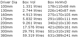
Table 2: Test Box Sizes.
The test box must be unlined and well sealed. 18 mm thick wood is fine, and 12 mm would do for the boxes of less than 10 litres. There is no need to add any bracing or strengthening as only very low level signals will be used with the box. If you add anything to the inside of the box it will count against the volume inside, which you need to know accurately.
4.4.3 Basket Volume/Cone Volume
If you are intending to mount your loudspeaker with its basket facing inside the test box, you need to subtract the basket volume of your drive unit from the test box internal volume in order to arrive at the actual volume that will be left inside the box once your loudspeaker is mounted to it. If you are mounting your loudspeaker with its basket facing outside the test box, you need to add the volume of the cone volume to the test box internal volume in order to arrive at the actual volume that will be left inside the box once your loudspeaker is mounted to it. Therefore you need to know either one of these volumes.
To determine the basket volume, carefully cover the basket with cling film/food wrap. Make sure you don't make it tight on the basket - you don't want it to tear and it must be able to be pushed a little into the gaps between the basket. Then get a bucket or bowl and fill it right up to the brim with water. Now carefully lower the drive unit into the bucket or bowl such that the surface of the water comes up to where the basket will mount flush to the box. The amount of water displaced is your drive unit volume. You can find out the volume by refilling the bucket or bowl with water from a measuring jug and seeing how much it takes to fill again.
To determine the cone volume, carefully cover the cone with cling film/food wrap. It only needs to be gently laid over the cone as it will need to move down with the filling. You can use either water, couscous or rice from a measuring jug to find out the volume - just fill up level to where the basket will mount flush to the box. Remove the filling afterwards with a small cup or scoop.
I prefer to mount the basket inside the test box, hence use the first method, as you need to know the basket volume anyway for when you do any modelling on your actual box. It also avoids the cone being depressed by the filling, which could be significant or possibly damaging if the suspension is very weak and the travel small. For connections I just drill a hole wide enough to accommodate common figure-8 wire in the opposite panel to the loudspeaker opening, then seal it in place with hot melt or epoxy glue.
4.4.4 Vas
Now you can mount your loudspeaker to the test box. Use the method for finding Fs as previously but, record the new frequency as Fc. Use the Loudspeaker Toolkit spreadsheet again and enter the new data gathered. The spreadsheet will calculate a few parameters and display them all together.
4.5.1 Fb
Using the current source set-up described previously and shown in Figure 4, calibrate your system. With the drive unit mounted to the box and all crossovers, etc. in place, but the vent covered over by a secure means (I clamp a slab of wood over it), swap out the 10 ohm resistor for your loudspeaker. Start from 100 Hz (for a bass drive unit) and sweep the sine wave generator down in frequency just a few Hz at a time and look for a high point on the volt meter reading. Tweak the sine wave generator until you reach the very highest reading you can get. Record the frequency as Fc.
Remove the cover from the vent and starting from 100 Hz and sweep the sine wave generator down in frequency just a few Hz at a time and look for a high point on the volt meter reading. Tweak the sine wave generator until you reach the very highest reading you can get. This is one of the two points of maximum impedance. Record the frequency as Fh. Now continue sweeping the frequency down a few Hz at a time and look for another high point on the volt meter reading. As before, tweak the sine wave generator until you reach the very highest reading you can get. Record the frequency as Fl.
Calculate the true value of Fb by the following equation (all you need is a simple calculator):
Fb = sqrt (Fh² + Fl² - Fc²)
4.5.2 Ql
Now set the sine wave generator to Fb and read off the volt meter to get the impedance and record this as Zmin. Remember that we calibrated earlier to give 10 mV per ohm, so if your volt meter reads 52 mV this corresponds to 5.2 ohms. Check your calibration data to see if you need to adjust the reading you took.
In the Loudspeaker Toolkit spreadsheet there is a second tab labelled "Vented". Use this sheet and enter the new data gathered. The spreadsheet will calculate a few parameters and display them all together for you.
Referring back to section 4.2 on calibration, if your calibration resistor was 10.2 ohms you would adjust the volume control to give 204 mV (giving 20 mV per ohm) or 408 mV (giving 40 mV per ohm). Then you must remember to divide the volt meter reading by 2 or 4 to get the actual impedance.
All content on this website Copyright © 2005-2025 Richard Read, unless otherwise stated. For commercial use please contact me.