
My relay has been designed to be compact and easy to use, and most importantly to pass audio signals both large and small without introducing switching or distortion. There are no moving contacts to create arcs or weld together so it has a long life and will actually protect your loudspeakers, as it has a high DC breaking capacity.
Because there is no wetting current requirement, it can even be used as an output muting relay for pre-amps.
Designed with DIY audio builders in mind, the trigger will accept any DC voltage from 3V to 16V and pulls less current than any power relay coil - approx 13mA - and does not have any back EMF. It can drop in any circuit where a relay coil of 3.3V, 5V, or 12V is used. The drive requirements are ideal for the latest generation of microcontrollers and single board computers such as Arduino and Raspberry Pi. Also works great with ESP P33.
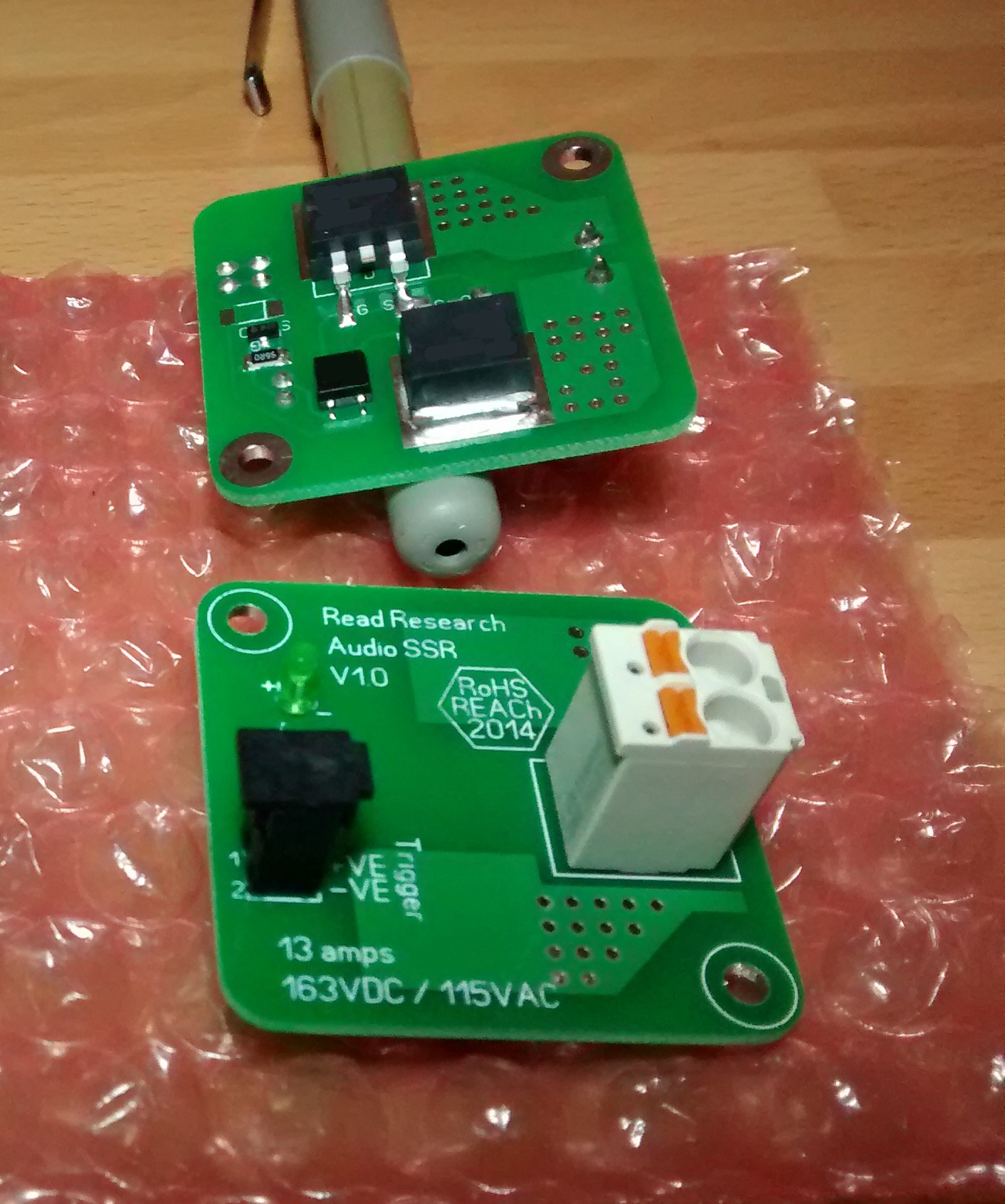
The large relay is rated at 9.9 amps continuous, 120V DC or 84V AC (max ±60V rails). This relay is good for ESP P101 running on 56V rails with 8 ohms or 4 ohms. For more efficient amps running on 56V rails keep to 8 ohm loads.
These are real world ratings and will take that all day long, they are not simply the MOSFET ratings (which are much higher). The limitation is down to how much heat the MOSFETs can dissipate.
Higher voltage and higher current versions are available at extra cost. Please contact for more details.

Overview

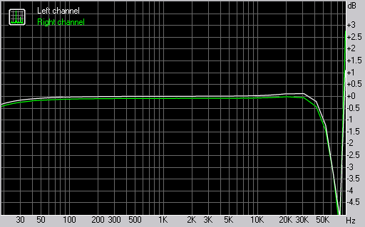
Frequency response. Green trace is system baseline, white is relay. Roll off at low frequency is due to measuring system, the relay is good down to DC.

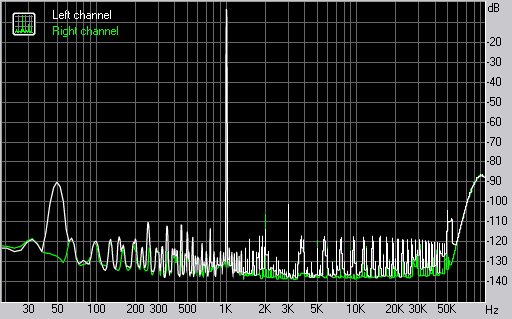
Total harmonic distortion. Green trace is system baseline, white is relay. Bump at 50Hz is just mains pickup due to unshielded wires.

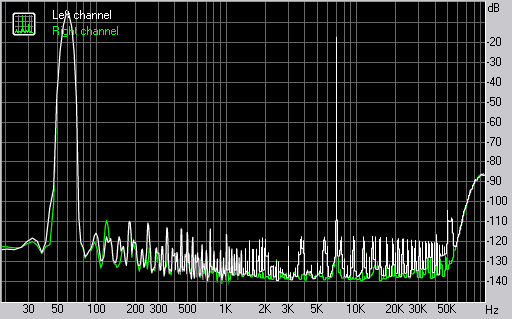
Intermodulation distortion. Green trace is system baseline, white is relay.
A PCB mounted LED will light up when the relay is triggered, this however limits the lowest trigger voltage to 5V. A version without the LED is available for 3.3V systems. Please contact for more details.
The MOSFETs have been carefully chosen so that a transient voltage supressor (TVS) is not required to protect the relay from back EMF (which will occur during a protective disconnection event). However, if you wish to apply belt and braces there is no harm to be done by connecting a 90V reverse stand-off (Vr) 600W (for the small relay) or 120V Vr 1500W (large relay) bidirectional TVS across the load (loudspeaker).
The module comes fully built, tested and burned in.

Creepage and clearance distances are no less than 2.5mm between trigger and power switching, or between power switching connections. Also between power switching and mounting spacers.
The large relay PCB is 40mm wide by 38mm high. The mounting holes are 3mm diameter, 32mm apart in the x-axis and 30mm apart in the y-axis. The recommended fixing is M3x12 threaded (hex) spacers.
All content on this website Copyright © 2005-2025 Richard Read, unless otherwise stated. For commercial use please contact me.